Introduction
In this guided exploration (BESP-1), we will see how the productive structure of a steam plant cycle can be constructed and how it allows one to calculate the exergy balance of the system.
Note that in a second guided exploration (BESP-2) this method is used to build the exergy balances of various cycles which have been presented in other guided explorations:
- regenerative gas turbine (ED C-M2-V2)
- refrigeration machine (ED S-M3-V9)
- steam cycle with reheat and extraction (ED C-M1-V5)
- single pressure combined cycle (ED C-M3-V1)
Typology of the problems posed and associated difficulties
A productive structure is a graph allowing to represent the production or consumption of exergy of the various units of an energy system. It is made up of productive and dissipative units (PDU), junctions and branches.
Each PDU is characterized by its own product flow, but can also have other outlet flows or sub-products. To produce them, it consumes external resources or products provided by other units. At each junction, a product flow is obtained by summing up inlets of the same nature but from different origins.
One of the great advantages of productive structures is that they make it possible to automate to a very large extent the establishment of exergy balances, even for complex energy systems, while this task can prove to be a journey full of pitfalls.
To use them, it is not necessary to master all their complexity: it is enough first of all to implement the method that we propose in this guided exploration. Further deepening the underlying concepts will be possible afterwards if necessary.
Implementation in Thermoptim
Versions 2.6 and 2.8 of Thermoptim include an editor for productive structures.
Loading the steam power plant model
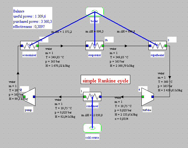
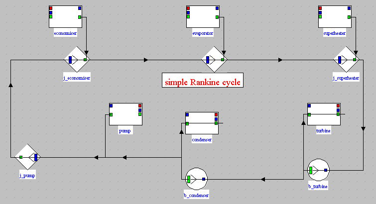
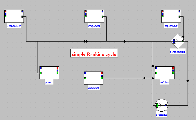
This is the simple steam plant cycle which is the subject of guided exploration S-M3-V7.
The synoptic view of this cycle is given below.
Loading the model
Click on the following link: Open a file in Thermoptim
You can also:
- either open the "Project files/Example catalog" (CtrlE) and select model m6.4 in Chapter 6 model list.
- or directly open the diagram file (steam_ref_P.dia) using the "File / Open" menu of the diagram editor menu, and the project file (steam_ref_P.prj) using the "Project files/Load a project" simulator menu.
Loading the editor of productive structures
You access the editor of productive structures by pressing Ctrl B or by selecting the line "Editor of productive structures" in the "Special" menu of the simulator.
If you can't do it, click this button
This window is similar to that of the diagram editor, with less functionality.
We recognize on its palette the icon of the process-points ![]() to represent the
inlet and outlet flows, that of the productive or dissipative units
PDU
to represent the
inlet and outlet flows, that of the productive or dissipative units
PDU ![]() , and those of the junctions
, and those of the junctions ![]() and branches
and branches ![]() .
.
Its Special menu includes three lines that do not appear in the usual Thermoptim diagram editor.
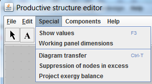
- Diagram transfer allows you to automatically generate a productive structure from the physical diagram and a project file
- Suppression of nodes in excess makes it possible to remove from the diagram certain junctions or certain branches
- Project exergy balance automatically builds the
exergy balance
We will specify later how to implement these features.
We build a productive structure either by hand by selecting the icons on the palette, placing them on the work plan, and connecting them by links, in a similar way to that used to constitute a physical diagram, or automatically by generating a productive structure from the simulator and the physical diagram.
Productive structure of the steam cycle
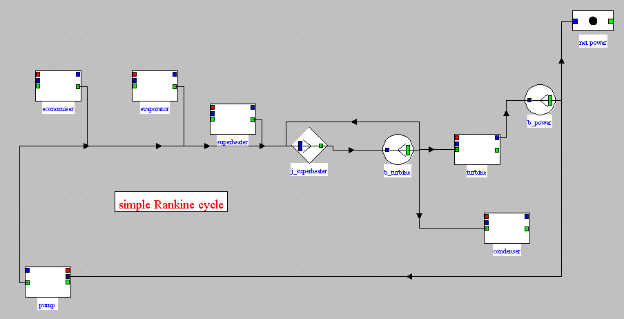
The productive structure of the steam plant is given below.
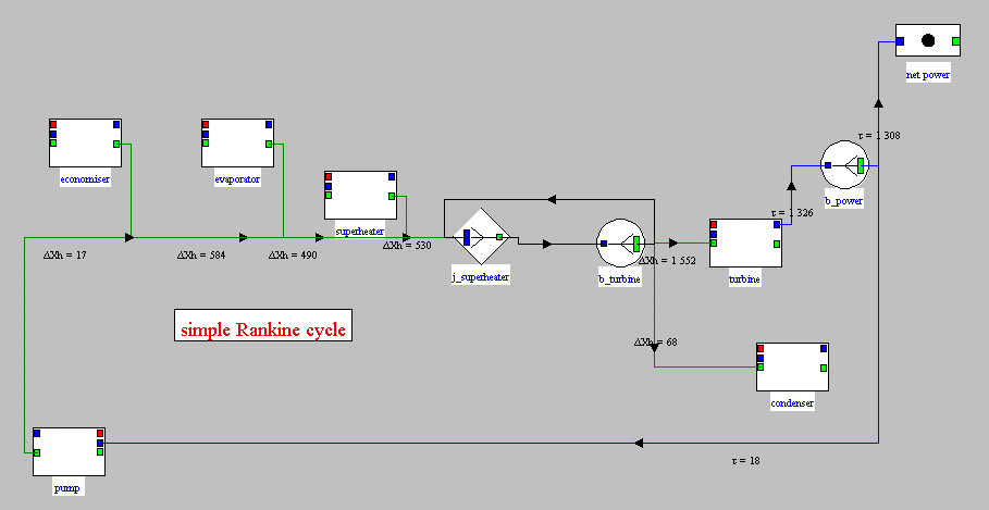
This productive structure is interpreted as follows: the steam power plant is a machine which receives an external exergy input in the boiler, which corresponds to the three productive units at the top left of the screen, and by internal recycling, exergy is provided to the pump, at the bottom left of the screen.
This exergy is partly converted into mechanical form in the turbine and partly dissipated in the condenser. The net power is the fraction of mechanical power not recycled.
The figure below shows the correspondences which exist between the physical diagram and the productive structure.
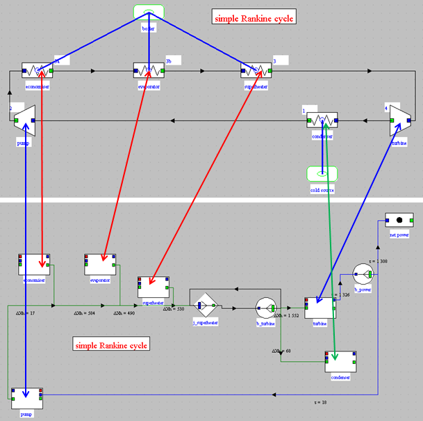
Each component of the diagram corresponds to a productive or dissipative unit (PDU).
These are connected to links that account for the fluxes of exergy variations in the system studied.
The junction downstream of the PDUs representing the pump and the three elements of the boiler makes it possible to add the variation of their exergy, which determines the exergy available for the downstream component, which is in this case a junction connected to a branch.
Downstream are the turbine and condenser PDUs. The former is connected to the pump and a process-point representing the net power.
Steam cycle exergy balance
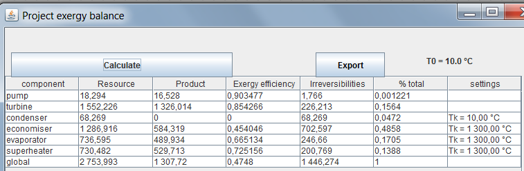
The figure below shows the exergy balance of the steam plant. The only information that had to be added to that of the usual Thermoptim project and the previous productive structure are the temperatures of the sources with which the power plant exchanges heat. We have assumed that they are worth 10 °C for the condenser, and 1300 °C for the boiler.
We will now return to these results and give some explanations on how they were obtained.
Exergy balances of the components
Let's start at the end. To establish the exergy balance of the complete model, Thermoptim bases itself on the information contained in the production structure and in the project, but it lacks, however, some data which are provided to it in the screens of the component exergy balances.
Double clicking the productive unit opens a screen which allows some settings in order to calculate component exergy resources and products, as well as irreversibilities and exergy efficiency, which, by shortcut, we denote by establishing the exergy balance of the component.
Once these settings are entered the component exergy balance can be calculated.
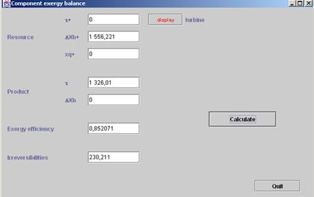
This figure shows the screen of a turbine PDU whose exergy balance can be determined without specific settings: the exergy resource is provided by the fluid exergy variation (Delta Xh+), the product is the mechanical power (tau), and the exergy efficiency and irreversibilities are also determined
When the component is of the exchange type, different possibilities exist.
- If it is a fluid inlet or outlet, which corresponds to a process-point connected only upstream or downstream, its total exergy (physical and chemical) must be taken into account. Note that this may influence the overall balance because the methods of calculating various exergy properties may differ according to the authors;
- If it is a fluid outlet rejected in the
environment, the exergy is lost, which corresponds to an
irreversibility. If on the contrary this exergy has an external
value, it is an exergy product without irreversibility. The exergy
calculation screen is provided with an option to specify this
(Valuable exergy);
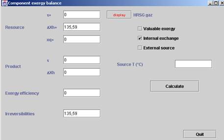
- When internal heat exchanges occur, as for instance in combined cycles, the exergy loss calculation must also be modified: it is equal, in absolute terms, to the algebraic sum of the exergy variations of both fluids exchanging heat. The component exergy balance screen has an option (Internal exchange) for this setting (see figure opposite). We shall see later that, in the overall exergy balance, the exergy variations of both fluids are displayed between brackets, the two exchange processes being grouped next to one another for clarity;
- Lastly, when heat exchange takes place with an external energy source, the heat-exergy involved must be assessed, which requires knowledge of the source temperature. This information may be entered in the exergy balance screen. The exergy calculation screen is provided with an option to specify this case (External Source) as well as a field for entering the source temperature.
For throttlings, the input exergy is the inlet relative exergy, and the output exergy the outlet relative exergy. The irreversibility is equal to their difference.
To be able to draw up the overall exergy balance of a system, you must first set each of the PDU screens. Once this work has been carried out, the overall balance can be calculated automatically.
Creation of the productive structure of the steam cycle
Creation of a productive structure
Recall that you access the productive structure editor by pressing Ctrl B or by selecting the "Productive structure editor" line in the "Special" menu of the simulator screen.
If you can't do it, click this button
Then activate line "Diagram transfer" of the "Special" menu of this editor.
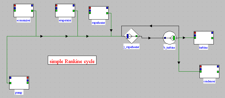
The automatically generated productive structure you get is given below.
Two dividers and three mixers are in series. Select the line "Suppress nodes in excess" and select, for dividers and mixers, the option "OK (except the physical model) ". The productive structure becomes:
In addition, as the PDUs and the nodes are positioned automatically in a manner analogous to the physical diagram, it is often preferable to move them slightly to obtain better readability.
Rework the structure, by shifting components from left to right or right to left. The result you get is close to this:
This diagram is not yet completely set. If we try to build the full project exergy balance ("Special" menu of the editor), we obtain the result in the figure below.
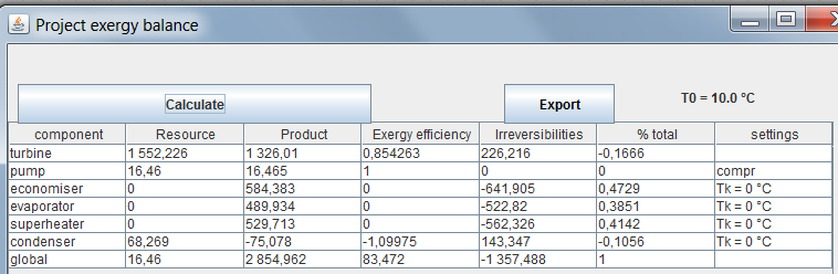
The last column, titled "settings", gives some summary information on the settings considered: the pump is an external exergy input (compr), because it is not connected to the turbine, and the condenser and the boiler are considered to be exchanging heat-exergy with a source at 0 °C, which is obviously absurd.
In the productive structure, the mechanical coupling between the turbine and the pump is missing. We represent it by a divider at the turbine outlet, with two branches, one representative of this coupling, and the other a link with a new process-point highlighting the net power available.
To end up building the productive structure, we still have to set the temperature of outside sources with which heat-exergy is exchanged, i.e. the boiler and condenser. We respectively choose 1300 °C and 10 °C).
The exergy balance of the project can now be recalculated. It is
given below and provides, for each component, the values of the
incoming exergy (resource), outgoing exergy (product), of its exergy
efficiency which qualifies it intrinsically, independently of the
other components, of irreversibilities, and their share in the total,
which qualifies it relatively.
For example, the pump has an exergy efficiency of around 90%, but its share in the total of irreversibilities is only 1.22%.
If we want to improve the performance of this cycle, the distribution of irreversibilities allows us to know which components are the ones to focus on.
The turbine, the evaporator and the superheater each represent only about 15% of irreversibilities, while nearly 49% take place in the economizer.
We must therefore clearly begin by taking a particular interest in
it. It is the object of the reheat and the extraction cycles studied
in guided explorations C-M1-V3 and C-M1-V5.
Conclusion
As you have seen, the creation of the productive structure is done without great difficulty. It just requires a little bit of attention, and the results it achieves far outweigh this extra work when looking at the exergy balance of a system.
Note that, if we are just trying to draw up an exergy balance, there is no need to fine-tune the productive structure. It is enough to make the mechanical connections, to set the temperatures of the external sources and to specify the outgoing flows whose exergy is valued externally (Valuable exergy).
The important thing is that all the component energy balance screens are correctly set.
You will find more detailed information on this subject in the following two pages of the Thermoptim-UNIT portal:
Productive structures and exergy balances
Quantitative analysis of cycles, energy and exergy
balances
In order to automatically create a productive structure in Thermoptim, you must first have a model of the system studied, that is to say its diagram and a correctly set project file. In fact, Thermoptim needs all the information contained in the model so that the productive structure is constructed correctly.
Let us specify that, for reasons which it is useless to develop here, during the automatic generation of the productive structure, to each component of the diagram are associated a PDU and a node, i.e. either a junction, or a branch. It follows that nodes of the same kind can be connected in series in the first productive structure generated, and that some are in excess. As it is useless to keep them all, Thermoptim has a functionality which allows to delete them automatically.
The procedure is as follows: