Introduction
In this guided exploration, we will review the productive structures associated with various cycles which have been the subject of guided explorations, with a view to establishing their exergy balances.
- regenerative gas turbine (ED C-M2-V2)
- refrigeration machine (ED S-M3-V9)
- steam cycle with reheat and extraction (ED C-M1-V5)
- single pressure combined cycle (ED C-M3-V1)
We assume that you are sufficiently familiar with the concepts used in the study of productive structures, such as those of productive or dissipative unit, junction, branching ...
If this is not the case, start by studying the guided exploration BESP-1: Exergy balance and productive structure of a simple steam cycle.
Brief reminders on productive structures
A productive structure is a graph allowing to represent the production or consumption of exergy of the various units of an energy system. It is made up of productive and dissipative units (PDU), junctions and branches.
Each PDU has a screen allowing to define certain parameters necessary to calculate the exergy balance of the component with which it is associated.
One of the great advantages of productive structures is that they make it possible to automate to a very large extent the establishment of exergy balances, even for complex energy systems, while this task can prove to be a journey full of pitfalls..
To use them, it is not necessary to master all their complexity: it is enough first of all to implement the method that we propose in this guided exploration. Further deepening the underlying concepts will be possible afterwards if necessary.
Implementation in Thermoptim
Versions 2.6 and 2.8 of Thermoptim include an editor for productive structures.
Regenerative gas turbine
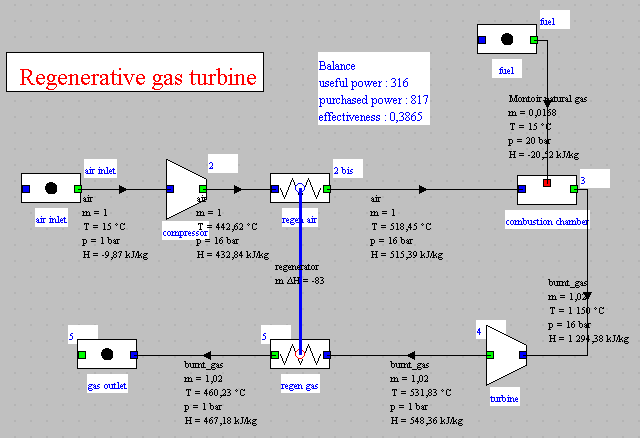
This is the regenerative gas turbine cycle which is the subject of guided exploration C-M2-V2.
The synoptic view of this cycle is given below.
Loading the model
Click on the following link: Open a file in Thermoptim
You can also:
- either open the "Project files/Example catalog" (CtrlE) and select model m6.5 in Chapter 6 model list.
- or directly open the diagram file (regen_GT_SP.dia) using the "File / Open" menu from the diagram editor menu, and the project file (regen_GT_SP.prj) using the "Project files/Load a project" menu from the simulator.
If the productive structure editor has not yet been opened, you can access it by pressing Ctrl B or by selecting the "Productive structure editor" line from the "Special" menu of the simulator screen.
You can then open the productive structure file (regen_GT_SP.str) using the "File/Open" menu of this editor.
Productive structure of the regenerative gas turbine
Here is the productive structure of the regenerative gas turbine.
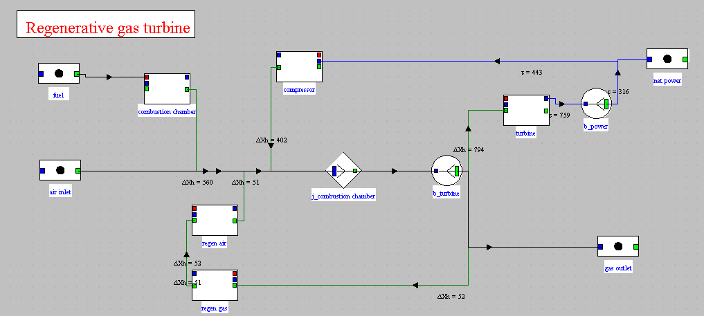
It is interpreted in the following way: the regenerative gas turbine is a machine which receives from the outside 560 kW of exergy in the combustion chamber, and, by internal recycling, on the one hand 402 kW of exergy from the compressor, and on the other hand 52 kW from the regenerator. This exergy is partly converted into mechanical form in the turbine (794 kW), partly returned to the regenerator (52 kW), and partly discharged to the outside (194 kW not readable in the figure). The net power corresponds to the fraction of mechanical power not recycled for the consumption of the compressor (316 kW).
You will note that the regenerator is represented by the two PDUs corresponding to the exchange processes that it connects.
The productive units representing the exchange processes of a heat exchanger are always linked together by a link intended to show the transfer of exergy which takes place within it.
Exergy balance of the regenerative gas turbine
The figure below shows the exergy balance of the regenerative gas turbine.
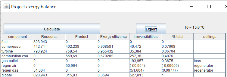
A special feature of the automatically generated exergy balance is that the internal exchangers are represented by two lines (here "regen gas" and "regen air" and that the contributions to the irreversibilities of the two fluids are represented algebraically, positively for the hot fluid and negatively for the cold fluid, the irreversibility of the entire exchanger being obtained by summing up these two values.
That is why they are indicated between brackets.
If we want to improve the performance of this cycle, the distribution of irreversibilities allows us to know which components are the ones to focus on.
Almost half of the irreversibilities take place in the combustion chamber, but unfortunately we do not know how to reduce them.
For the rest, 37% comes from the release of hot gases into the
atmosphere. The only solution to reduce them is to exploit the
enthalpy of these gases, for example in a combined cycle.
Refrigeration machine
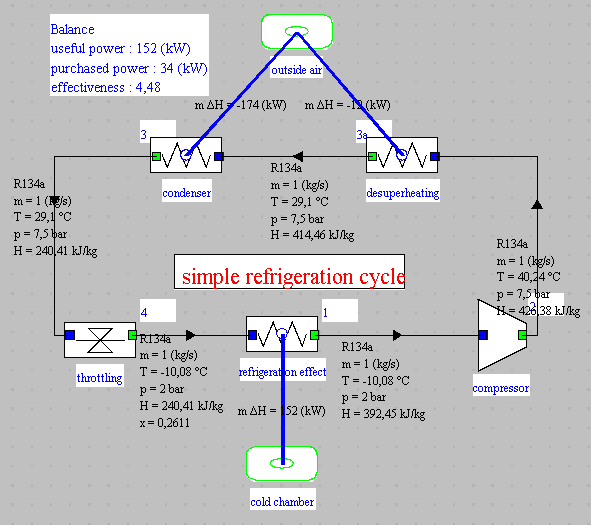
This is the cycle of the refrigeration machine which is the subject of the guided exploration S-M3-V9.
The synoptic view of this cycle is given below.
Loading the model
Click on the following link: Open a file in Thermoptim
You can also:
- either open the "Project files/Example catalog" (CtrlE) and select model m6.6 in Chapter 6 model list.
- or directly open the diagram file (refrig_light_SP.dia) using the "File / Open" menu from the diagram editor menu, and the project file (refrig_light_SP.prj) using the "Project files/Load a project" menu from the simulator.
If the productive structure editor has not yet been opened, you can access it by pressing Ctrl B or by selecting the "Productive structure editor" line from the "Special" menu of the simulator screen.
You can then open the productive structure file (refrig_light_SP.str) using the "File/Open" menu of this editor.
Productive structure of the refrigeration machine
Here is the productive structure of the refrigeration machine.
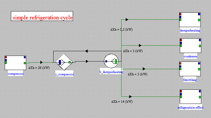
It can be interpreted as follows: the refrigeration machine receives an exergy supply from the outside in the compressor (28 kW). This exergy is partly converted in the evaporator (refrigeration effect, 14 kW), the rest being dissipated in the desuperheater (0.5 kW), the condenser (5 kW) and the expansion valve (throtlling, 5 kW).
Exergy balance of the refrigeration machine
The figure below shows the exergy balance of the refrigeration machine.
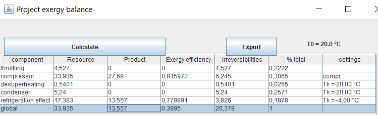
The only information that had to be added to that of the usual Thermoptim project and to the productive structure are the temperatures of the sources with which the refrigeration machine exchanges heat.
We took -4 °C for the evaporator and 20 °C for the desuperheater and the condenser.
This exergy balance is very interesting: while, with the machine's COP being 4.48, one might think that the machine is very efficient, its exergy efficiency is only around 40%.
An exergy balance is much better to qualify the performance of a refrigeration cycle than a simple enthalpy balance!
Steam cycle with reheat and extraction
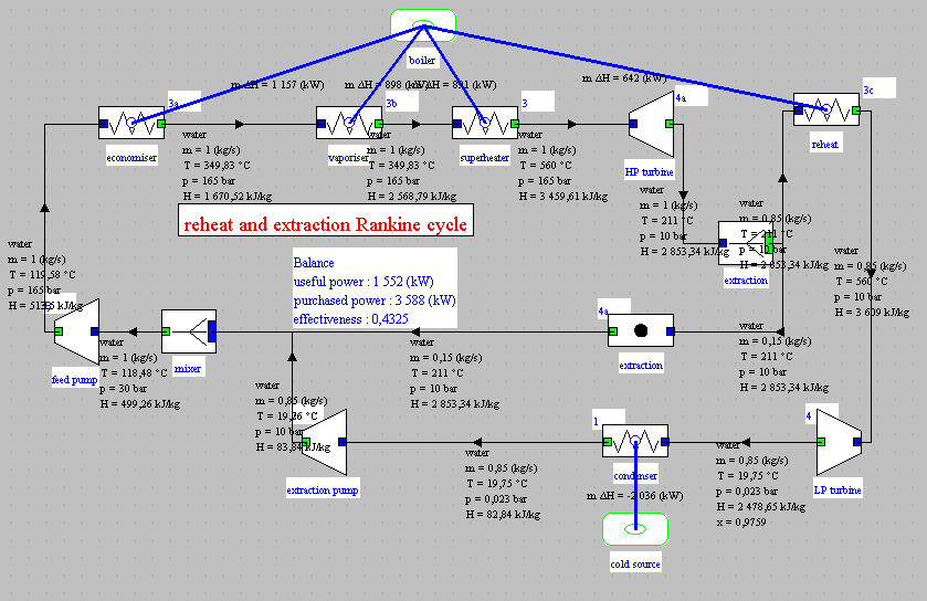
This is the steam cycle with reheat and extraction which is the subject of guided exploration C-M1-V5.
The synoptic view of this cycle is given below.
Loading the model
Click on the following link: Open a file in Thermoptim
You can also:
- either open the "Project files/Example catalog" (CtrlE) and select model m6.7 in Chapter 6 model list.
- or directly open the diagram file (steamExtrReheat_SP.dia) using the "File / Open" menu from the diagram editor menu, and the project file (steamExtrReheat_SP.prj) using the "Project files/Load a project" menu from the simulator.
If the productive structure editor has not yet been opened, you can access it by pressing Ctrl B or by selecting the "Productive structure editor" line from the "Special" menu of the simulator screen.
You can then open the productive structure file (steamExtrReheat_SP.str) using the "File/Open" menu of this editor.
Productive structure of the steam cycle with reheat and extraction
Here is the productive structure of the steam cycle with reheat and extraction.
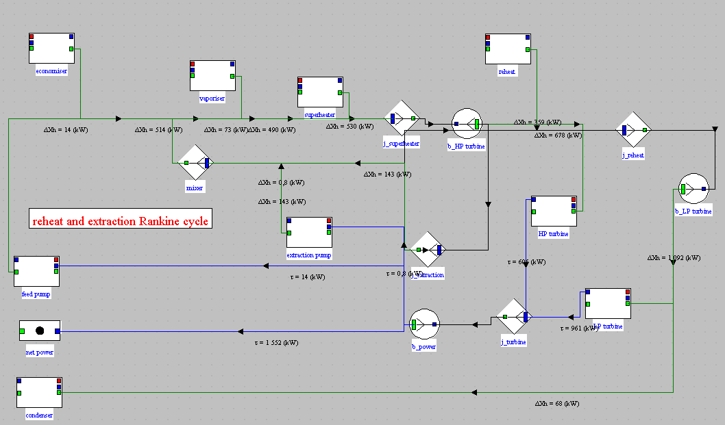
It is interpreted in the following way: the steam plant is a machine which receives from the outside a supply of exergy in the boiler, which are the four productive units at the top of the screen, and, by internal recycling, an exergy supply from the two pumps, in the middle left of the screen. This exergy is partly converted into mechanical form in the turbines and partly dissipated in the condenser. The net power corresponds to the fraction of mechanical power not recycled for the consumption of the pumps.
When constructing the production structure, care must be taken to keep the mixer which represents the feedwater tank. Indeed, it receives several water flows at different temperatures, and is therefore the seat of irreversibilities.
Exergy balance of the steam cycle with reheat and extraction
The figure below shows the exergy balance of the steam cycle with reheat and extraction.
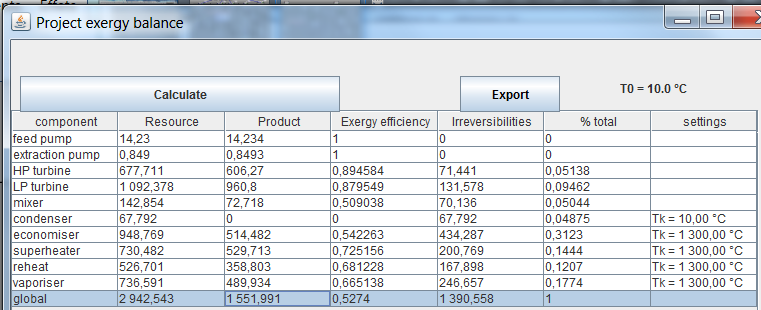
You will note that the feedwater tank appears in the balance sheet ("mixer").
Even if its exergy efficiency is very low (47%), its contribution to the overall balance remains low (5.3%).
If we compare this balance with that of the simple cycle below, we note that it well reflects the improvements brought by reheat and extraction.
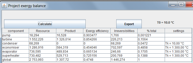
The irreversibilities in the economizer went from 45.4% to 31% of the total, and the exergy efficiency from 47.5% to 52.7%.
Single pressure combined cycle
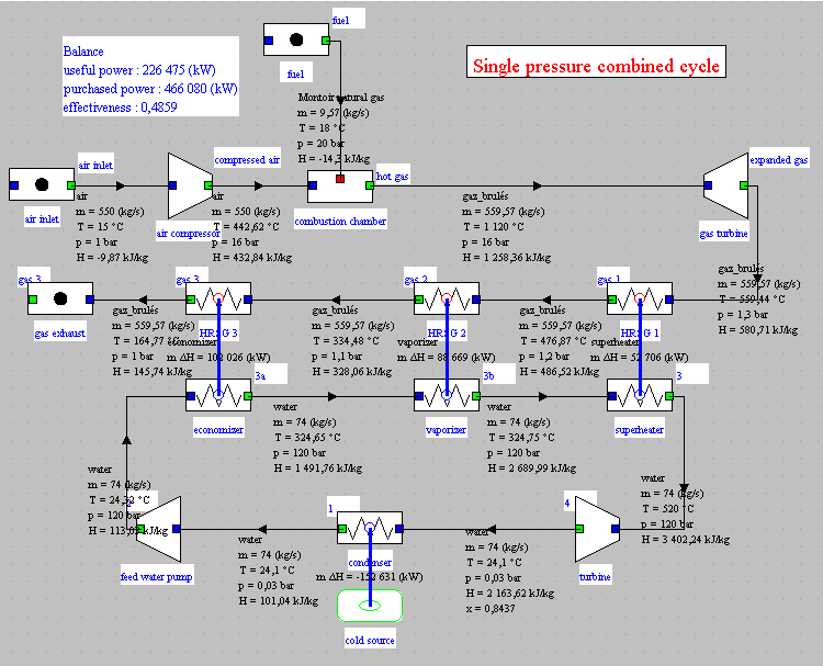
This is the single pressure combined cycle which is the subject of guided exploration C-M3-V1.
The synoptic view of this cycle is given below.
Loading the model
Click on the following link: Open a file in Thermoptim
You can also:
- either open the "Project files/Example catalog" (CtrlE) and select model m6.8 in Chapter 6 model list.
- or directly open the diagram file (CC1P_En_SP.dia) using the "File / Open" menu from the diagram editor menu, and the project file (CC1P_En_SP.prj) using the "Project files/Load a project" menu from the simulator.
If the productive structure editor has not yet been opened, you can access it by pressing Ctrl B or by selecting the "Productive structure editor" line from the "Special" menu of the simulator screen.
You can then open the productive structure file (CC1P_SP.str) using the "File/Open" menu of this editor.
Productive structure of the single pressure combined cycle
Here is the productive structure of the single pressure combined cycle.
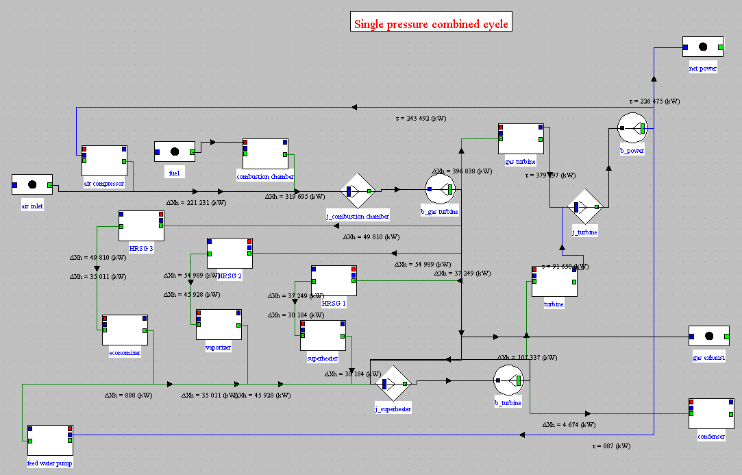
It is interpreted in the following way: the gas turbine receives from the outside a supply of exergy in the combustion chamber, and, by internal recycling, a supply of exergy from the compressor. This exergy is partly converted in the turbine and discharged to the outside in the exhaust gases, and partly transmitted to the steam cycle by the exchangers of the heat recovery steam generator (HRSG). This cycle also receives, by internal recycling, a supply of exergy from the pump. The available exergy is partially converted in the steam turbine, the rest being dissipated in the condenser.
You will note that the productive units representing the exchange processes of a heat exchanger are always linked together by a link intended to show the transfer of exergy which takes place within it, as we already pointed out in the step dedicated to the regenerative gas turbine.
Exergy balance of the single pressure combined cycle
The figure below shows the exergy balance of the single pressure combined cycle.
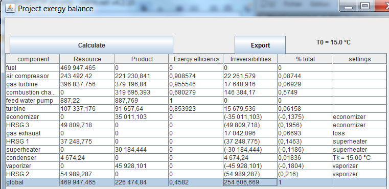
As we have already pointed out, a peculiarity of the automatically generated exergy balance is that the internal exchangers are represented by two lines and that the contributions to the irreversibilities of the two fluids are represented algebraically, positively for the hot fluid and negatively for the fluid cold, the irreversibility of the entire exchanger being obtained by summing these two values.
That is why they are indicated between brackets.
The distribution of irreversibilities is also eloquent here. Almost 60% comes from the combustion chamber, but we know that they are inevitable.
The rest are distributed more or less uniformly. What we can
especially notice is that the share of the gases discharged to the
atmosphere is here very reduced (6.7%), whereas it represented 38% in
the exergy balance of the regenerative gas turbine.
Conclusion
The great advantage of using productive structures is that exergy balances are automatically established, while spreadsheet calculations require to take a lot of precautions if we want to avoid errors.
The indications given in the last column of the project exergy balance allow the setting of the productive structure to be checked quite easily, and therefore limit the risk of error.
Note that, if we are just trying to draw up an exergy balance, there is no need to fine-tune the productive structure. It is enough to make the mechanical connections well, to set the temperatures of the external sources and to specify the outgoing flows whose exergy is valued externally (Valuable exergy).
The important thing is that all the component energy balance screens are correctly set.
You will find more detailed information on this subject in the following two pages of the Thermoptim-UNIT portal:
Productive structures and exergy balances
Quantitative analysis of cycles, energy and exergy
balances