Introduction
In this guided exploration (DTNN-1), we will see how the surface of a heat exchanger can be determined and how its behavior in off-design conditions can be calculated.
Note that a second guided exploration (DTNN-2) relates to the sizing and study in off-design mode of a piston compressor used to supply a compressed air storage tank.
Typology of problems posed and associated difficulties
The problem arises because the NTU heat exchanger calculation method which is implemented in the Thermoptim core can only determine the product UA of the global heat exchange coefficient U by the surface A of the exchanger, without the two terms being evaluated separately.
For further explanations, we suggest you refer to the page of the Thermoptim-UNIT portal which deals with heat exchangers.
To be able to go further and separate these two terms, it is necessary to carry out what we call a technological sizing of the exchanger.
This is a relatively complex problem that you should understand before you can use it. It is presented in this page of the Thermoptim-UNIT portal, which we strongly recommend that you read before anything else.
To be able to size an exchanger, that is to say calculate its surface, it is necessary on the one hand to choose its geometric configuration, and on the other hand to calculate U, which depends on this configuration, on the thermophysical properties of fluids, and on the operating conditions.
Implementation in Thermoptim
Versions 2.7 and 2.8 of Thermoptim allow you to perform technological sizing and off-design studies. For this, they introduce screens complementary to those which allow the usual phenomenological modeling to be carried out.
They define the geometric characteristics representative of the different technologies used, as well as the parameters necessary for calculating their performance. For a given component, they obviously depend on the type of technology chosen.
The calculations are carried out in extensions of the core of the software package, and in particular in programs called pilots or drivers of Thermoptim.
They are so called because they take control of the software by driving it to perform specific operations not available in the core screens.
There are many types of pilots. Two categories of pilots make it possible to carry out technological sizing studies, generic pilots and specific pilots.
The former are by nature multipurpose but can only perform simple calculations, while the latter, defined specifically for a particular model, can perform much more complex operations.
In this guided exploration, we will only use a generic pilot.
Loading the air-water exchanger model
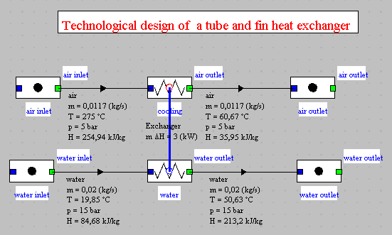
Consider a tube and fin exchanger intended to cool 0.66 kg/min (11.7 g/s) of air leaving a compressor at 5 bar and 275 °C thanks to a flow of 1.17 kg/min (20 g/s) of cold water passing through a coil made up of two tubes in parallel. The diameter of the tubes is 15 mm, and their thickness 1.5 mm. The spacing between the fins is 3 mm. In this example, the wall and fouling resistances are neglected. The effectiveness of the exchanger is assumed to be 0.84.
Loading the model
Click on the following link: Open a file in Thermoptim
You can also:
- either open the "Project files/Example catalog" (CtrlE) and select model m4.2 in Chapter 4 model list.
- or directly open the diagram file (exampleAirExchanger.dia) using the "File/Open" menu from the diagram editor menu, and the project file (exampleAirExchanger.prj) using the "Project files/Load a project " menu from the simulator.
Open the exchanger screen and calculate it.
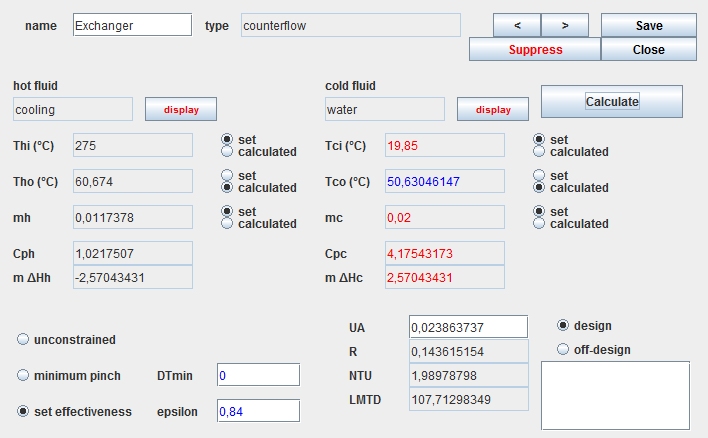
The thermal power exchanged is 2.57 kW.
The setting of this model is completely classic and does not require any particular explanation.
The only remark at this stage is that the flows were entered in kg/s and not in g/s, whereas Thermoptim would allow to do so.
It is indeed necessary to operate in this way because Thermoptim carries out technological sizing studies using the units of the International SI System.
The only sizing result that we arrive at is the product UA of the heat exchange coefficient by the surface of the exchanger, without it being possible to determine the values of each of these two factors. Here UA = 0.02386 kW/K, or 23.86 W/K.
Procedure to be implemented
Using the generic pilot
Loading the generic pilot
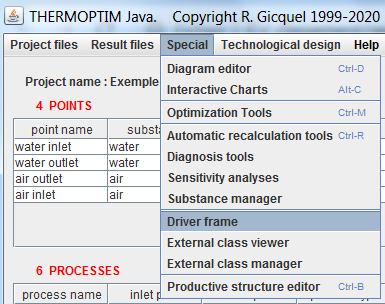
The generic technological design pilot can be loaded from the simulator screen. To do this, activate the "Driver frame" line in the "Special" menu.
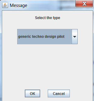
Then select the line "generic techno design pilot" from the list of available drivers, and click "OK".
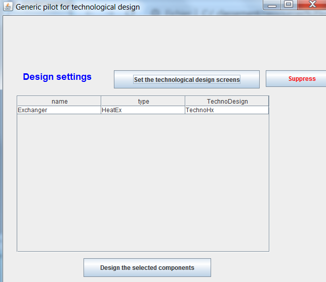
The pilot screen opens. Click on "Set the technological design screens".
A row appears in the table, corresponding to the exchanger.
It indicates that it is a heat exchanger (HeatEx), and that it is considered to be a simple exchanger (TechnoHx).
It is possible to change this type by double-clicking on the table row. This is what should have been done if it was an evaporator or a vaporizer, but this is not the case here.
The technological screen is now created.
To access it, return to the simulator screen, and activate the line "Technological design screens" in the "Technological design" menu, or type Ctrl T.
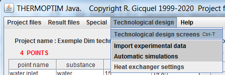
The window allowing access to the existing technological design screens is displayed.
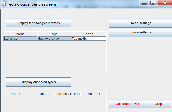
Double-clicking on the table row opens the technological design screen for the selected component.
Technological design screen of an exchanger
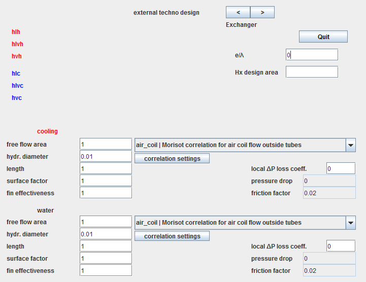
Here is the technological design screen of an exchanger set by default.
The study of the calculation of the heat exchange coefficients and of the pressure drop shows that, in addition to the surface of the exchanger A, two geometrical quantities play a particularly important role: the passage cross-section assigned to the fluid Ac, and the hydraulic diameter dh. When the heat exchange coefficients of fluids are very different, various devices such as fins are used to compensate for the difference between their values. We then speak of enhanced surfaces, which can be characterized by a surface factor f and a fin effectiveness eta0.
These four parameters are those used in Thermoptim to characterize the heat exchanges for each fluid. We add the length of the exchanger for certain calculations such as pressure drop.
In the technological design screen of the exchangers, the following conventions are adopted:
- the type of configuration (here "air-coil") is selected from a drop-down list
- "free flow area" represents the passage section Ac
- "hydr. diameter" is the usual hydraulic diameter dh
- "length" is the length of the exchanger (used for the calculation of the boiling number Bo and for the calculation of the pressure drop, not yet implemented in the two-phase case)
- "surface factor" is the surface factor f for enhanced surfaces
- "fin effectiveness" is the effectiveness of fins eta0
In our case, there are fins on the outside of the tubes only. The last two parameters therefore have the value 1 for the cold fluid but not for the hot fluid.
However, the default correlation is not correct. By clicking on "air-coil | Morisot correlation ...", the list of possible choices is displayed.
For the hot fluid, the one that interests us is "ext_tube Colburn correlation ...."
For the cold fluid, it is "int_tube Mac Adams correlation ....".
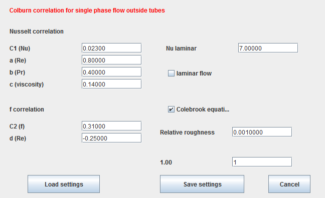
Colburn's default correlation setting is given below. You can access it by clicking on the technological screen of the exchanger, on the "correlation settings" button located below the correlation type.
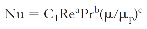
The values of the coefficients C1, a, b and c are those of this classic formula giving Nusselt as a function of Reynolds, Prandtl and viscosity.
If the default values do not suit you, you can modify and save them using the "Save settings" button.
Thermal resistance of the wall
The e/lambda parameter located at the top slightly right of the screen represents the thermal resistance due to the fluid wall (this is the ratio of the thickness of the wall to its thermal conductivity lambda). We will neglect it here.
Setting of the exchanger
Let us recall the constructive hypotheses that we assumed to be retained for the exchanger: cold water passes through a coil made up of two tubes in parallel. The diameter of the tubes is 15 mm, and their thickness 1.5 mm. The spacing between the fins is 3 mm. We further assume that the length of the exchanger is 0.9 m.
It is necessary to begin by determining the hydraulic diameters dh and the passage sections Ac of the two fluids.
Inside the tubes, dh is given, and the calculation of Ac is very simple: it is equal to the product of the number of tubes per the unit section.
Outside the tubes, the calculations are a little more complicated. dh is equal to 4 times the section divided by the wet perimeter.
As for Ac, it is the transverse surface offered to the passage of air. It is assumed that the fins multiply by 4 the exchange surface, with an effectiveness equal to 0.8.
Detailed explanations of the calculations to be made are given in this page of the Thermoptim-UNIT portal. A link will allow you to download a spreadsheet showing how these calculations are performed.
This document provides more information on this setting.
It only remains to enter these values in the technological screen of each of the two fluids.
To make your task easier, you can simply read these values in the setting file corresponding to this exchanger.
To do this, go to the window giving access to the technological design screens, and click on the "Read parameters" button located at the top left, and select the file "echAirEauparam.par".
All the parameters of the exchanger are then updated.
Once the technological screen is set, return to the pilot screen.
Then click on "Design the selected components" after selecting the table row.
The technological screen is calculated. Here is the result.
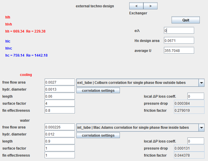
For the exchanger, the surface determined is equal to 0.0671 m2, the overall exchange coefficient being equal to 355.7 kW/m2/K.
On the left of the screen are displayed the values of the heat exchange coefficient h within each fluid and those of their Reynolds numbers.
In the case of a single phase fluid like here, only one line is indicated.
The hot fluid appears in red, the cold in blue, according to the usual conventions.
The pressure drop values (in bar) and the friction factor are displayed on the right of the screen, in the setting of each fluid.
Refer to volume 4 of the Thermoptim reference manual for more details.
Geometric configuration of the exchanger
Taking into account the sizing which has just been carried out, the exchanger will consist of two 90 cm tubes arranged in a serpentine on 3 layers and crossing metal sheet plates with a total surface of 0.31 m2 separated from each other by 3 mm.
If you want to be precise, you enter this length as the value of the "length" field on the water side, and 6 cm on the air side, which allows you to refine the estimate of pressure losses.
Off-design behavior
Once the exchanger has been sized, its behavior in off-design conditions can be studied directly from its screen in the simulator.
The "off-design" calculation mode in fact makes it possible to calculate, by the NUT method, the exchanger in off-design mode considering that its two inlet temperatures and its two flow rates are set.
Thermoptim updates the upstream links of the exchanger from the processes, then calculates the downstream temperatures and balances the exchanger on the enthalpy level, the UA having the value entered in the field of the exchanger screen. The points and processes associated with the model are updated according to the results.
However, when using the generic pilot that we loaded previously, no correction is automatically made on UA to take into account the evolution of the exchange coefficients as a function of flow rates and temperatures.
It is therefore necessary to operate in the following manner:
- 1) modify the values of the inlet temperatures and flow rates of the two processes
- 2) calculate the heat exchanger in off-design mode from its usual screen
- 3) perform a new design calculation of the exchanger to determine the new value of U
- 4) calculate the product UA of the area initially determined and the new value of U
- 5) modify UA accordingly in the exchanger screen
- 6) restart the calculation in off-design mode, repeating
operations 2 to 6 until the values stabilize.
As an example, let's examine how our exchanger would behave if the flow rate and the temperature of the incoming air were changed from 0.01174 to 0.01 kg/s and from 275 to 300 °C respectively.
Proceed as follows:
- modify the inlet conditions of the exchanger in Thermoptim, choose the "off-design" option instead of "design" in the exchanger screen;
- recalculate the exchanger several times, until the values stabilize;
- finally click on the "Design the selected component" button in the generic driver screen.
- The new value of U is calculated: it is worth 338.7 kW/m2/K, while the exchange surface changes to 0.0705 m2.
- Multiplying this value by the initial area of the exchanger, you get a new value of UA, equal to 0.022725, which you enter in the corresponding field of the exchanger screen.
- Repeat operations 2 and 3: a more precise estimate of U is obtained, taking into account the new setting. It is worth 338.66 kW/m2/K, while the exchange surface increases to 0.0672 m2.
- Change UA accordingly, which takes you to the exchanger screen
below.
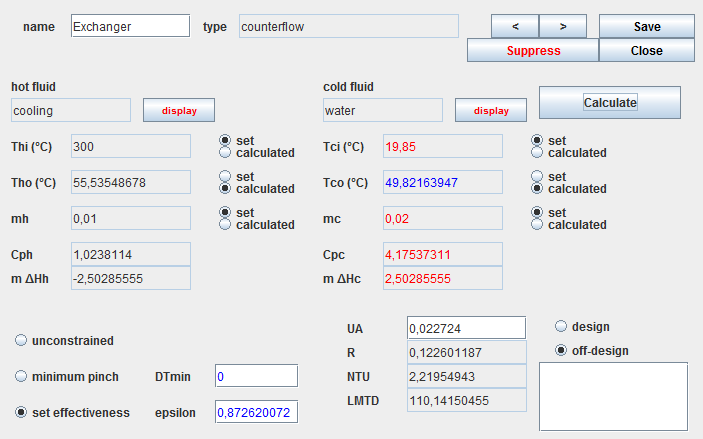
All the explanations on this example are provided in the educational breadcrumb on the heat exchangers of the Thermoptim-UNIT portal.
In the above, we manually modified the value of UA in the exchanger, the technological screen having been constructed by the generic pilot. This way of doing things has the advantage that it does not require any programming, but it is a bit long to put into practice when several iterations must be carried out. It would therefore become tedious if you had to simulate the off-design behavior of the exchanger for a wide variation range of its operating conditions.
In this case, it is far better to automate these updates using a specific driver.
Conclusion
This exploration allowed you to discover how to calculate the surface area of a finned heat exchanger and the specific settings it requires, using the generic technological sizing pilot.
This generic pilot makes it possible to carry out technological sizing of relatively simple models and to study their behavior in off-design conditions when the different components are not too strongly coupled.
When the systems to be studied are more complex, it becomes necessary to use specially programmed pilots.
Many examples of such models are available in the Thermoptim model library.
Finally, it should be noted that the exchanger that we used here will be reused in the DTNN-2 guided exploration on cooled positive displacement compressors.
Using the Thermoptim technological sizing screens, it is possible to calculate the overall heat exchange coefficient and to deduce the area necessary to transmit the desired thermal power.
The concepts underlying these calculations being relatively complex, we recommend that you read the sections relating to exchangers in volume 4 of the Thermoptim reference manual, much more detailed than what it is possible to indicate in this guided exploration.
The procedure is as follows: