Sizing of a displacement air compressor

Using the generic pilot and a specific driver

Introduction

In this guided exploration (DTNN-3) on positive displacement compressors, we detail the calculation and sizing of a piston compressor used to supply a compressed air storage tank.

Note that a second guided exploration (DTNN-1) deals with the determination of the surface of a heat exchanger and its behavior in off-design conditions.

Functionally, compressors are devices used to increase the pressure of fluids passing through them.

They are used for many industrial applications, for refrigeration, air conditioning, transportation of natural gas ...

Technologically speaking, compressors can be grouped into two main classes:

For further explanations, we suggest you refer to the page of the Thermoptim-UNIT portal which deals with positive displacement compressors.

Special mention should be made of air compressors, used as a source of power in public works and construction and in factories, pneumatic tools having many benefits. The example presented here focuses on this type of device.

The example we are dealing with here is intended to diagnose the problems and show how they can be resolved without the overall system being too complicated. For specialists, it will seem a bit simplistic, but for beginners it is already quite difficult to treat completely.

Typology of problems posed and associated difficulties

The study of the compressors in an energy system has very different levels of difficulty depending on the objectives that we pursue.

The most basic approach is to calculate the outlet temperature when the compression ratio and isentropic efficiency are known. If the flow-rate involved is also known, the compression work can be deduced directly.

The inverse problem is solved also simply: knowing the compressor inlet and outlet states, you can determine the isentropic efficiency of the device.

To go further and determine the isentropic efficiency and the flow through a given displacement machine, we have to perform more complicated calculations, requiring a thorough knowledge of compressor operation.

We will call technological design calculations for determining the displacement of a compressor knowing the laws giving its volumetric and isentropic efficiencies.

This is by the way a general problem in energy systems studies: as long as one is satisfied to carry out cycle studies without trying to size the geometry of the components, the calculations are much simpler than when one wishes to closely analyze their internal behavior.

Once the displacement determined, allowing to geometrically characterize the compressor, another problem remains to be treated: that of its behavior when operating conditions differ from those used in the design.

We call this problem the study of its off-design behavior.

It can be a higher level of complexity than the technological design, because it may require solving large systems of nonlinear equations when several components are coupled together.


This is a relatively complex problem that you should understand before you can use it. It is presented in this page of the Thermoptim-UNIT portal, which we strongly recommend that you read before anything else.

When trying to accurately represent the behavior of a given compressor, it is necessary to characterize it by:

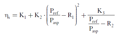
The theory shows that the main factor on which these quantities depend is the compression ratio Pref/Pasp, ratio of the discharge pressure to the suction pressure.

rendement volumétrique

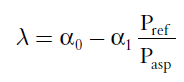
Generally, a first order polynomial law is enough to represent the evolution of the volumetric efficiency as a function of the compression ratio.

To properly represent the isentropic efficiency eta, we need more parameters. The law we will retain uses 5:

rendement isentropique

To size a compressor, it is necessary to know these laws.

Identification of their parameters can usually be made on the basis of data provided by the manufacturer.

Implementation in Thermoptim

Versions 2.7 and 2.8 of Thermoptim allow technological sizing and off-design studies. For this, they introduce screens complementary to those which allow the usual phenomenological modeling to be carried out.

They define the geometric characteristics representative of the different technologies used, as well as the parameters necessary for calculating their performance. For a given component, they obviously depend on the type of technology chosen.

The calculations are carried out in extensions of the core of the software package, and in particular in programs called pilots or drivers of Thermoptim.

They are so called because they take control of the software by driving it to perform specific operations not available in the core screens.

There are many types of pilots. Two categories of pilots make it possible to carry out technological sizing studies, generic pilots and specific pilots.

The former are by nature multipurpose but can only perform simple calculations, while the latter, defined specifically for a particular model, can perform much more complex operations.

Loading the cooled displacement compressor model

We propose to study the behavior of a volumetric air compressor which fills a storage of compressed air of given volume at variable pressure.
The compressed air is cooled before storage thanks to an air-water exchanger of the type presented in the DTNN-1 guided exploration on exchangers, to which we refer you for more details.

The compressor sucks an air flow of 0.66 kg/min (11.738 g/s) at 1 bar and 26.85 °C, and compresses it at 5 bar.

Loading the model

Click on the following link: Open a file in Thermoptim

You can also:

  • either open the "Project files/Example catalog" (CtrlE) and select model m19.4 in Chapter 19 model list.
  • or directly open the diagram file (Example_VsCompressor.dia) using the "File/Open" menu from the diagram editor menu, and the project file (Example_VsCompressor.prj) using the "Project files/Load a project " menu from the simulator.

If you display the values ​​in the diagram editor, you get the synoptic view below.

The compressor screen is given below.

The setting of this model is completely classic and does not require any particular explanation.

The only remark at this stage is that the flows were entered in kg/s and not in g/s, whereas Thermoptim would allow to do so.

It is indeed necessary to operate in this way because Thermoptim carries out technological sizing studies using the units of the International SI System.

Compressor sizing

To size the compressor, we must have the parameters of the equations giving the volumetric and isentropic efficiencies.

We assume here that they have been determined from data provided by the manufacturer.

The calculation of the compressor corresponds to the steps below:

In design mode, we determine the rotation speed to provide the desired flow or the displacement corresponding to a given rotation speed. The calculation is performed taking into account the inlet and outlet pressures and the flow value entered in the flow-rate field of the compressor.

In off-design mode, the compression ratio determines lambda and eta, which gives the compressor flow rate and outlet temperature.

Procedure to be implemented

The procedure is as follows:

  • open the generic technologcal design pilot
  • create the technological sizing screen of the compressor (which will also
  • create that of the heat exchanger)
  • open the window giving access to the technological design screens of the components
  • set the technological giving access to screen of the compressor
    perform its sizing

Using the generic pilot

Loading the generic pilot

The generic technological design pilot can be loaded from the simulator screen. To do this, activate the "Driver frame" line in the "Special" menu.

Then select the line "generic techno design pilot" from the list of available drivers, and click "OK".

The pilot screen opens. Click on "Set the technological design screens".

Two rows appear corresponding to the exchanger and the compressor, as in the figure below. Select the one for the compressor.

Its type is by default Compression, and its TechnoDesign VolumCompr. Since it is a positive displacement compressor, they are perfectly suitable. Double-clicking on this line would change the type of TechnoDesign, but this is not necessary here.


Technological screens are now created.


To access them, return to the simulator screen, and activate the line "Technological design screens" in the "Technological design" menu, or type Ctrl T.

The window allowing access to the existing technological design screens is displayed.

Double-clicking on one of the table rows opens the technological design screen for the selected component.

Technological design screen of a compressor

Here is the technological design screen of a compressor set by default.


The fields on the left side of the compressor technological screen allow you to enter the compressor characteristics:

Enter in these fields the parameter values, select "Calculate Vs" so that Thermoptim know that this value must be calculated, then return to the generic driver screen, and click "Design the selected components" after having selected its row.

To make your task easier, you can simply read these values ​​in the setting file corresponding to this compressor.

To do this, go to the window of the technological design screens, select the compressor line, and click on the "Read parameters" button located at the top left, and select the file "comprRefroidiDTNN.par".

All the compressor parameters are then updated.

Once the characteristic values ​​have been entered in these fields, and the "Calculate Vs" option has been selected so that Thermoptim knows that this value must be calculated, return to the generic pilot screen, and click on "Design the selected components".

Here is the result you get.

The fields on the right side of the screen show calculated values of isentropic efficiency, mass flow and volumetric efficiency.

The displacement (0.0055 m3) was determined on the basis of the flow entered the compressor process, and other values from the parameter values. Once the displacement calculated, the "Calculate m" option is selected because it corresponds to the normal calculation mode of this TechnoDesign.

Technological design of the heat exchanger

The technological design of the cooling exchanger is the subject of DTNN-1 guided exploration, to which we recommend that you refer before going further.

Off-design calculations

Once the compressor has been sized, its behavior in off-design conditions can be studied by operating in two steps.

The technological screen is then recalculated.

We will assume that the compressor discharge pressure is now 8 bar and not 5.

Here is the result.

Thermoptim has correctly calculated the new isentropic efficiency and flow rate values, but it has not modified them in the compressor screen and in the air intake screen.

In order for them to be taken into account, they must be copied from the technological screen to the classic phenomenological screen.

Once these operations have been carried out and the compressor recalculated, the following result is obtained.

The same should be done for the heat exchanger, as explained in the DTNN-1 guided exploration.

In the above, we manually modified the values ​​of the isentropic efficiency and the flow rate, the technological screen having been constructed by the generic pilot. This way of doing things has the advantage that it does not require any programming, but it is a bit long to put into practice when several iterations must be carried out. It would therefore become tedious if you had to simulate the off-design behavior of the exchanger for a wide variation range of its operating conditions.

In this case, it is far better to automate these updates using a specific driver, as we will explain in the next step.


Using a specific driver

To illustrate the capacity of Thermoptim to perform calculations in off-design mode, we will study the behavior of a volumetric air compressor which fills a storage of compressed air of given volume at variable pressure. The compressed air is cooled before storage thanks to a water exchanger.

Loading the model

Click on the following link: Open a file in Thermoptim

You can also:

  • either open the "Project files/Example catalog" (CtrlE) and select model m19.5 in Chapter 19 model list.
  • or directly open the diagram file (Example_VsCompressorPilot.dia) using the "File/Open" menu from the diagram editor menu, and the project file (Example_VsCompressorPilot.prj) using the "Project files/Load a project " menu from the simulator.

When loading the project, the pilot screen opens. Click on "Initial settings" to create the technological screens and initialize them.

We find the settings made with the generic pilot.

Using this driver is much simpler, however.

Just enter the new outlet pressure in this screen so that the whole project is recalculated and updated when you click on the red button "Calculate".

If you return to the diagram editor and double click twice on the F3 key to update the displayed values, you get the following synoptic view.

You can thus modify the input and output parameters of the model and easily calculate the adaptation of the installation to its new operating conditions.

How to program the pilot is outside the scope of this guided exploration.

You will find all the explanations on this question in the Thermoptim-UNIT portal, and more particularly in this document.

Conclusion

This exploration allowed you to discover how to size a positive displacement compressor and the corresponding specific settings, using first the generic pilot of technological sizing, then a specific pilot.

The educational breadcrumb on the volumetric compressors of the Thermoptim-UNIT portal explains how to use this pilot on a practical level.